20 14 Steps with Pictures Circuit Diagram Current sensing example circuits - quiz 5. Overcurrent detection is used to: a) Alert when load current has exceeded a specified threshold b) Help ensure that electronic systems operate safely c) Help a control system decide if power needs to be turned off d) All of the above 6. The INA302 and INA303 are examples of: a) A current sense comparator
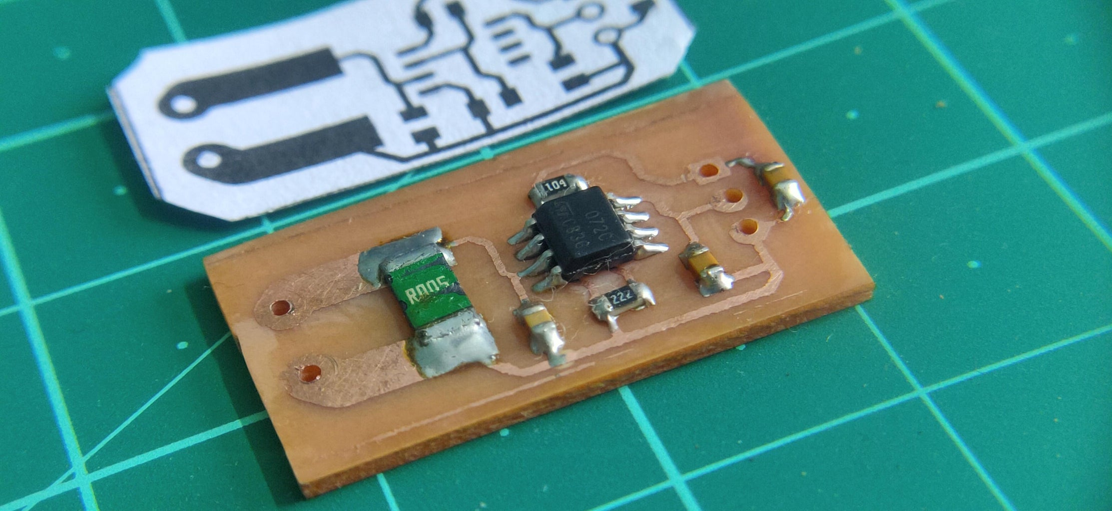
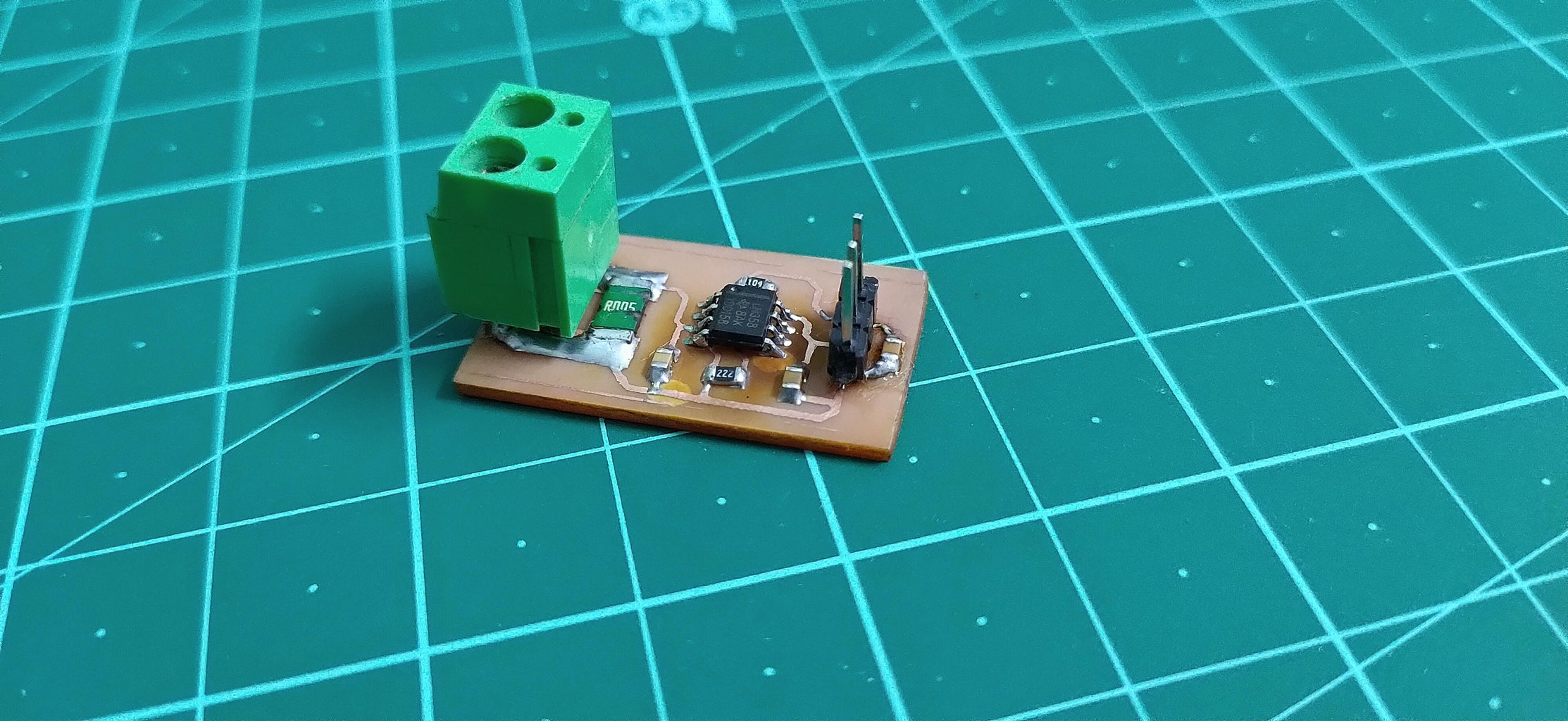
This project features a compact design and an all SMD component based circuit, making this sensor module very compact for it's range. This current sensor can easily be used for measuring currents up to 15 Amps constant and can even handle about 20 Amps peak. It is unlikely that any particular circuit shown will exactly meet the requirements for a specific design, but the suggestion of many circuit techniques and devices should prove useful. allow for very wide range current sensing. In this circuit a six decade range of current pulled from the circuit input terminal is converted to an output
PDF Low Circuit Diagram
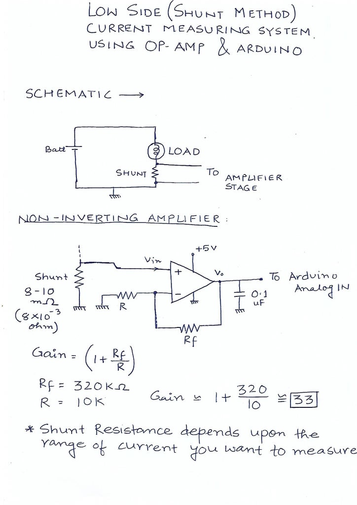
Assume that the required specifications of the low-side current detection circuit are as follows. Current sensing range: ILOADmin to ILOADmax = 30 A to 50 A Current sensing error: Err = 7% Current sensing frequency: fsense = 1 kHz Voltage drop at shunt resistor: ΔVSHUNTmax = 50 mV Maximum output voltage of the op-amp: VOmax = 3.3 V
Current Sensing Tutorial: Introduction This project attempts to provide a brief review of the current sensing techniques underlying 2 common types of current sensors: the conventional DC current sensor and the hall-effect sensor. Breadboard 1 To provide a convenient workspace for the circuit . DC Motor 1 Acts as a load in the tested circuit
An Engineer's Guide to Current Sensing (Rev. B) Circuit Diagram
fundamentals of current sensing circuits. It introduces current sensing resistors, current sensing techniques and describes three typical high-side current sensing implementations, with their advantages and disadvan-tages. The other current sensing implementations are beyond the scope of this application note and reserved Ways to measure current: 1- Indirect method: such as current transformers (in the figure) and Hall effect sensors, which relies on Faraday's law of induction to sense current in a circuit and convert it to a proportional voltage. These methods are suitable more for high current systems. 2- Direct method: which relies on Ohm's law which states that V = I x R. The idea is that you could build such a current sensor yourself and that's what this article is all about. The only hurdle is to measure low voltage drop. In the modules that I have dealt with so far, the shunt had a resistor of 0.1 ohms. Even with a fairly high current of, for example, an ampere, the voltage drop is just one hundred millivolts.
challenges associated with designing an accurate current-measurement circuit for cost-optimized applications. Approaches range from using general-purpose operational amplifiers to analog-to-digital converters, whether stand- This e-book was created to further simplify the current sensing design process by helping you quickly and efficiently
