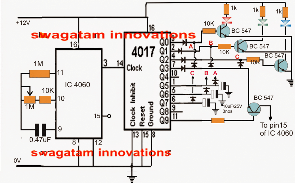
LIGHTING CONTROLS AUTOMATIC Circuit Diagram Finally, if you're interested in designing your own traffic light controller system, you can follow the design principles outlined in the circuit diagram. With the right set of components and a basic understanding of electronics, you should be able to design your own circuit for efficiently controlling traffic lights. The clock signal from the debouncing stage is fed to pin 14 of IC 4017 which will switch the light strip's illumination color. By pressing any button on the IR remote you can switch to your desired illumination color, after white color which is the last one you can turn off the LEDs in the light strip and by pressing a button on the remote we can cycle through all the colors again.
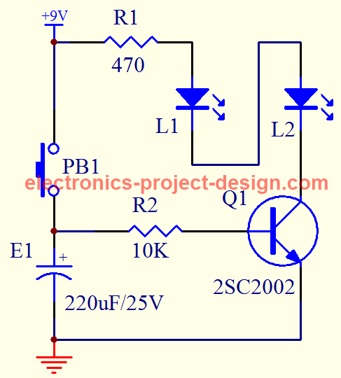
In some places, there is no AC mains power available, right. So, in such cases, we cannot use AC mains based street light circuits. Thats where a solar-powered automatic LED street light system becomes a smart solution, right. So now the 3rd circuit design below shows how we can make a small solar street light circuit using very few parts. How The Night Light Circuit Works. The photoresistor and the 100 kΩ resistor make up a voltage divider. When there is a lot of light, the photoresistor will have low resistance, which means the voltage divider gives a low output voltage. So the transistor is off and cuts off the current to the LED. Which means no light. As the name of the project "Traffic Light Control Circuit" suggests, the fundamental idea of this simple electronic project is to control the traffic via lighting signals. It can be used to avoid vehicular collisions and traffic jams as the system ensures the smooth flow of traffic even on the busy routes.
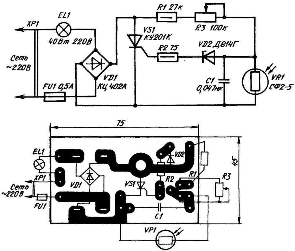
IC 555 Automatic SOLAR Street Light Circuit: How to Build Circuit Diagram
This is a small low-cost automatic street light controller circuit based on the 555 timer and an LDR. Apart from the street lights, this circuit can be used in areas where you need to control anything on the light basis. So many other projects can be built using the 555 Timer IC. I will try to add more projects based on the 555 Timer. By using this system manual works are 100% removed. Here we design an automatic street light controller using relay and LDR which senses the light actually like our eyes. We know LDR (Light Dependent Resistor) has been used in many applications and properly employing in-circuit LDR can act as a perfect light-sensing element.

Here the simple traffic light controller which is could be used to educate kids rudiments of traffic light guidelines. The circuit utilizes easily available electronic parts. It generally consists of rectifier diodes (1N4001), a 5V regulator 7805, two timers circuit using IC 555, two relays (5V, single-changeover), three 15W, 230V light bulbs One of the first things many do with it is to create a blinking light. But that's just one simple example of the many things you can do with this chip. You can also control motors, create an alarm, create a musical instrument, and much more. Let's start with an overview of the pins. 555 Timer Pinout